
NewsDetails
Design and Mechanical Performance Analysis of Overhead Line Fittings
author:Dachuan time:2026-03-25 10:44:59 Click:159
Design and Mechanical Performance Analysis of Overhead Line Fittings
Overhead line fittings are essential components used to connect, support, and protect conductors, insulators, and towers in power transmission and distribution systems. Their design and mechanical performance directly influence the safety, reliability, and longevity of the entire line. A comprehensive understanding of structural design principles and mechanical behavior is crucial for optimizing performance under various loading and environmental conditions.
1. Overview of Overhead Line Fittings
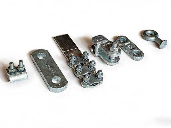
Overhead line fittings include:
Suspension clamps
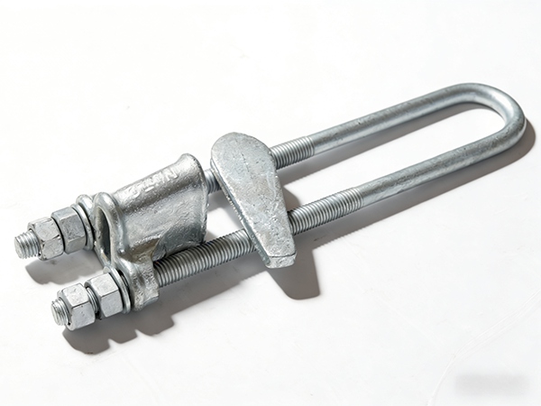
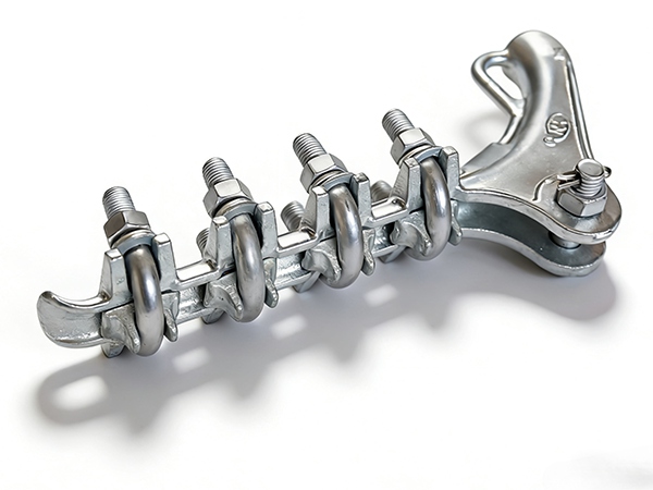
Tension (dead-end) clamps
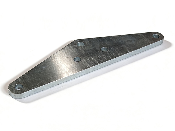
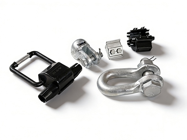
Linking fittings (clevis, shackles, yoke plates)
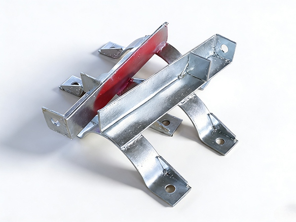
Spacers and dampers
Protective fittings (armor rods, arcing horns, corona rings)
These components ensure proper load transfer, conductor positioning, and electrical clearance throughout the transmission system.
2. Design Principles
2.1 Load-Oriented Design
Fittings must be designed to handle multiple types of loads:
Static loads: conductor weight and hardware mass
Dynamic loads: wind-induced vibration, galloping
Accidental loads: ice shedding, conductor breakage
Design must incorporate adequate safety factors to prevent mechanical failure under extreme conditions.
2.2 Stress Distribution Optimization
Efficient stress distribution is critical to avoid localized stress concentration:
Smooth geometrical transitions reduce stress peaks
Rounded edges and proper curvature improve fatigue life
Uniform load transfer between connected components enhances durability
Finite Element Analysis (FEA) is often used to simulate stress distribution and optimize design.
2.3 Material Selection
Material choice directly affects mechanical performance:
High-strength steel or alloy steel for load-bearing components
Aluminum alloys for lightweight and conductive fittings
Corrosion-resistant materials or coatings for harsh environments
Material properties such as yield strength, ductility, and fatigue resistance must align with design requirements.
2.4 Standardization and Interchangeability
Fittings should comply with standardized dimensions and interfaces:
Ensures compatibility across different manufacturers
Simplifies installation and maintenance
Reduces inventory and operational complexity
3. Mechanical Performance Analysis
3.1 Tensile Strength and Load Capacity
Tensile strength determines the maximum load a fitting can withstand without failure. Key indicators include:
Ultimate Tensile Strength (UTS)
Specified Mechanical Load (SML)
Safety factor (typically 2.5–3.0 for critical components)
Testing ensures that fittings meet or exceed design load requirements.
3.2 Fatigue Performance
Overhead line fittings are subject to cyclic loading due to wind-induced vibration:
Fatigue failure is a major concern for long-term operation
Proper material selection and surface finish improve fatigue resistance
Dampers and spacers help reduce vibration amplitude
Fatigue testing simulates long-term operational conditions.
3.3 Creep and Relaxation
Under constant load, materials may experience deformation over time:
Creep affects long-term dimensional stability
Relaxation may reduce clamping force in connectors
Design must account for these effects to maintain performance
3.4 Impact and Shock Resistance
Fittings must withstand sudden forces such as:
Ice shedding
Conductor breakage
Installation impacts
Materials with high toughness and ductility are preferred to absorb shock without fracture.
3.5 Corrosion Resistance
Corrosion significantly reduces mechanical strength over time:
Hot-dip galvanizing provides long-term protection
Coating thickness and uniformity are critical
In aggressive environments, additional coatings or stainless materials may be required
4. Structural Analysis Methods
4.1 Analytical Calculations
Basic mechanical calculations are used to estimate:
Stress and strain
Load distribution
Safety margins
These calculations form the foundation of initial design.
4.2 Finite Element Analysis (FEA)
FEA is widely used for advanced design optimization:
Simulates stress distribution under complex loading
Identifies weak points and stress concentration areas
Reduces the need for extensive physical prototyping
4.3 Experimental Testing
Laboratory and field tests validate design performance:
Tensile and compression tests
Fatigue testing
Environmental and corrosion testing
Testing ensures compliance with international standards and real-world conditions.
5. Failure Modes and Prevention
5.1 Common Failure Modes
Mechanical fracture due to overload
Fatigue cracking from cyclic stress
Corrosion-induced weakening
Loosening of connections
5.2 Preventive Measures
Use appropriate safety factors in design
Apply high-quality coatings and corrosion protection
Conduct regular inspection and maintenance
Optimize design to reduce stress concentration
6. Environmental and Operational Considerations
6.1 Wind and Vibration Effects
Aeolian vibration can cause long-term fatigue damage
Galloping can introduce large dynamic loads
Dampers and spacers are essential for mitigation
6.2 Temperature Variations
Thermal expansion and contraction affect stress levels
Materials must maintain mechanical properties across temperature ranges
6.3 Pollution and Moisture
Accelerate corrosion and material degradation
Require enhanced protective coatings and material selection
7. Lifecycle Performance and Optimization
Design for long service life with minimal maintenance
Balance initial cost with lifecycle performance
Use predictive maintenance based on monitoring data
Upgrade materials and coatings as technology advances
8. Conclusion
The design and mechanical performance of overhead line fittings are fundamental to the reliability and safety of power transmission systems. By integrating sound engineering principles, advanced analysis methods, and high-quality materials, fittings can withstand complex mechanical and environmental stresses over long service periods. Continuous improvement in design and materials will further enhance the efficiency and durability of modern power infrastructure.
References
IEC 61284 – Overhead lines – Requirements and tests for fittings
IEEE Standard 605 – Guide for Design of Substation Rigid-Bus Structures
CIGRÉ Technical Brochures on Overhead Line Performance
ASTM A153/A153M – Zinc Coating (Hot-Dip) on Iron and Steel Hardware
Blevins, R. D. Flow-Induced Vibration
 Recommended Products
 Contact us
—— Contact:Manager
—— Tel:+86 15631793633
—— Email:960244024@qq.com
—— Url:https://www.dachuan-power.com
—— Address:Liugusi Town, Hejian City, Cangzhou City, Hebei Province, China