
NewsDetails
Cracks in Power Iron Fittings: Causes and Inspection Methods
author:Dachuan time:2026-04-17 14:36:58 Click:193
Cracks in Power Iron Fittings: Causes and Inspection Methods
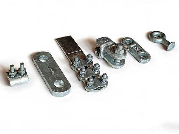
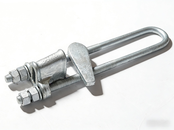
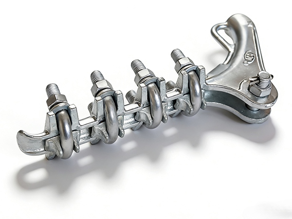
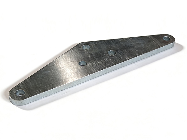
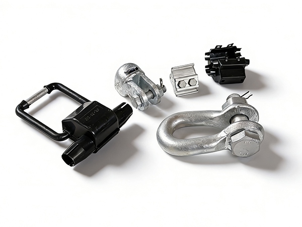
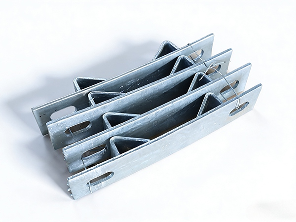
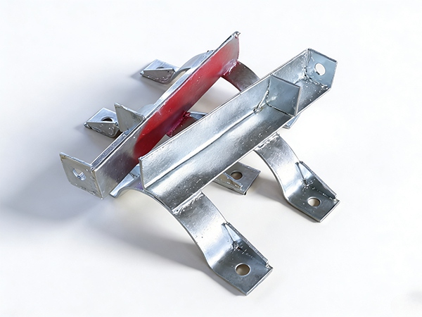
Cracks in power iron fittings are one of the most dangerous defects in overhead transmission and distribution systems. These fittings—such as clamps, clevises, cross arms, connectors, bolts, and shackles—operate under continuous mechanical loads and harsh environmental exposure. Even small cracks can rapidly propagate under cyclic stress, eventually leading to sudden failure of the component and potential line outages or safety accidents.
1. Overview of Crack Formation in Power Fittings
Cracks refer to material discontinuities that develop due to:
Mechanical overstress
Fatigue under repeated loading
Corrosion and environmental degradation
Manufacturing defects
Improper installation or assembly stress
Cracks may be surface-level or internal, and both types can significantly reduce structural integrity.
2. Main Causes of Cracks in Power Iron Fittings
2.1 Mechanical Overload
When applied stress exceeds material strength.
Causes:
Extreme wind pressure
Ice loading on conductors
Unexpected tension increase in lines
Characteristics:
Sudden crack initiation
May lead to immediate fracture in brittle materials
2.2 Fatigue Cracking
The most common crack type in service.
Causes:
Wind-induced vibration
Conductor galloping
Long-term cyclic loading
Process:
Microcrack initiation at stress concentration points
Gradual propagation over time
Final sudden failure
2.3 Stress Concentration
Cracks often start at weak geometric locations.
Sources:
Sharp corners or edges
Bolt holes and threaded regions
Machining defects
2.4 Corrosion-Induced Cracking
Corrosion weakens the material and promotes crack growth.
Causes:
Moisture and humidity
Coastal salt spray
Industrial pollution
Types:
Pitting corrosion leading to crack initiation
Stress corrosion cracking (SCC) under tension
2.5 Manufacturing Defects
Internal flaws from production stage.
Examples:
Casting porosity
Forging folds or inclusions
Welding defects
These defects act as crack initiation points under load.
2.6 Improper Heat Treatment
Uneven hardness distribution
Reduced toughness
Increased brittleness
2.7 Improper Installation
Over-tightening bolts
Misalignment of components
Uneven load distribution
3. Types of Cracks in Power Fittings
3.1 Surface Cracks
Visible to naked eye or magnification
Often caused by fatigue or corrosion
3.2 Subsurface Cracks
Hidden beneath surface layer
Require ultrasonic or advanced inspection
3.3 Through Cracks
Extend completely through component
High risk of sudden failure
3.4 Intergranular Cracks
Occur along grain boundaries
Common in corrosion or heat-affected zones
4. Effects of Cracks on Power Systems
Reduced mechanical load capacity
Sudden brittle failure under stress
Increased risk of conductor drop
Accelerated corrosion at crack sites
Reduced service life of fittings
Potential large-scale power outages
5. Inspection Methods for Crack Detection
5.1 Visual Inspection
Method:
Direct observation using naked eye or magnifying tools
Field patrol inspections
Detects:
Surface cracks
Rust lines indicating crack development
Limitations:
Cannot detect internal cracks
5.2 Magnetic Particle Inspection (MPI)
Applicable for: Ferromagnetic materials
Method:
Magnetic field applied to component
Iron particles gather at crack locations
Advantages:
High sensitivity for surface and near-surface cracks
Widely used in field maintenance
5.3 Ultrasonic Testing (UT)
Method:
High-frequency sound waves penetrate material
Reflections indicate internal discontinuities
Detects:
Internal cracks
Subsurface defects
5.4 Dye Penetrant Testing (DPT)
Method:
Liquid dye applied to surface
Penetrates cracks and reveals defects under developer
Suitable for:
Surface crack detection in non-porous materials
5.5 Radiographic Testing (RT)
Method:
X-ray or gamma-ray imaging
Produces internal structure image
Advantages:
Detects deep internal cracks
High accuracy
5.6 Acoustic Emission Monitoring
Detects sound waves emitted by growing cracks
Useful for real-time structural health monitoring
6. Crack Prevention Measures
6.1 Design Optimization
Reduce stress concentration areas
Add fillets and smooth transitions
Improve load distribution paths
6.2 Material Improvement
Use high-strength low-alloy (HSLA) steel
Improve toughness and fatigue resistance
Select corrosion-resistant materials for harsh environments
6.3 Surface Protection
Hot-dip galvanizing
Zinc-aluminum coatings
Duplex protective systems
6.4 Manufacturing Quality Control
Strict forging and casting inspection
Heat treatment optimization
Non-destructive testing before delivery
6.5 Installation Control
Correct torque application
Proper alignment of fittings
Avoid overloading during assembly
6.6 Maintenance and Monitoring
Regular inspection schedules
Early crack detection and repair
Replacement of damaged components
7. Crack Repair Methods
7.1 Welding Repair (Limited Use)
Applicable for non-critical components
Requires post-weld heat treatment
7.2 Mechanical Reinforcement
Add external reinforcement plates
Reduce stress on cracked area
7.3 Component Replacement
Recommended for severe or through cracks
Ensures full restoration of safety
8. Future Development Trends
AI-based crack detection systems
Smart sensors for real-time crack monitoring
Digital twin simulation of crack propagation
Self-healing coating materials
Advanced fatigue-resistant alloys
9. Conclusion
Cracks in power iron fittings are a critical failure risk that can lead to sudden structural failure and power system disruption. They are mainly caused by fatigue, corrosion, overload, manufacturing defects, and improper installation. Effective inspection methods such as magnetic particle testing, ultrasonic testing, and visual inspection are essential for early detection. Through improved design, high-quality materials, protective coatings, and regular maintenance, crack occurrence can be significantly reduced, ensuring safe and reliable operation of power transmission systems.
References
IEC 61284 – Overhead lines – Requirements and tests for fittings
ASTM E1444 – Magnetic particle testing
ASTM E1417 – Liquid penetrant testing
ISO 17638 – Non-destructive testing of welds
ASM Handbook – Failure Analysis and Prevention
CIGRÉ Technical Brochures on Overhead Line Hardware Defects and Reliability
 Recommended Products
 Contact us
—— Contact:Manager
—— Tel:+86 15631793633
—— Email:960244024@qq.com
—— Url:https://www.dachuan-power.com
—— Address:Liugusi Town, Hejian City, Cangzhou City, Hebei Province, China