
NewsDetails
Power Fitting Installation Best Practices and Safety Guidelines
author:Dachuan time:2026-06-22 21:07:55 Click:73
Power fitting installation requires meticulous attention to assembly procedures, torque specifications, and safety protocols that ensure reliable mechanical connections and electrical performance throughout overhead line service life. These installation practices, developed through decades of field experience by power line hardware manufacturers and utility engineering organizations, address the diverse challenges encountered during construction, maintenance, and emergency restoration of power distribution and transmission systems. Understanding proper installation techniques, quality verification methods, and safety requirements enables line construction crews to achieve consistent installation quality that maximizes system reliability and minimizes maintenance requirements.
Pre-Installation Inspection and Preparation
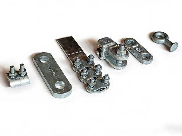
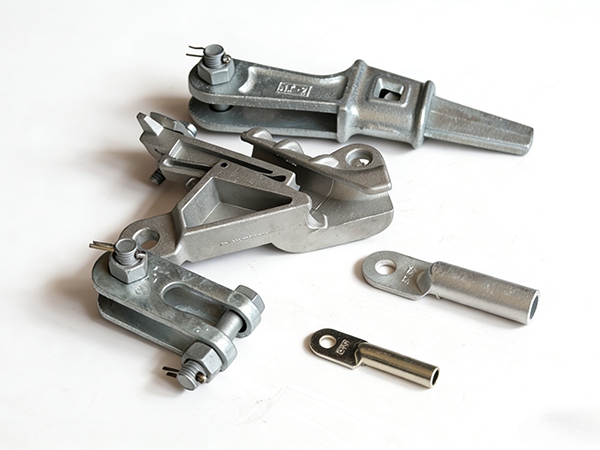
Pre-installation inspection verifies that all hardware components match bill of materials specifications, exhibit acceptable surface condition without shipping damage or corrosion, and carry proper identification markings for traceability. Galvanized surfaces must be free from bare spots, zinc flaking, or mechanical damage that compromises corrosion protection. Threaded fasteners must engage smoothly without cross-threading, and compression connectors must match conductor dimensions specified in manufacturer compatibility charts.
Conductor preparation includes removal of surface oxide layer through wire brushing (for aluminum conductors), application of oxide inhibitor compound at connection interfaces, and verification that conductor diameter falls within connector design range. Conductor end preparation for compression connectors requires clean, square cuts without bird-caging or strand separation that could interfere with proper connector installation. Professional hardware suppliers provide pre-installation checklists and conductor preparation specifications that ensure field crews achieve consistent installation quality across project locations.
Torque Application and Fastener Management
Proper bolt torque application achieves design clamping force that creates reliable mechanical connections while preventing fastener overstress that causes yield or fracture. Torque values specified by hardware manufacturers (typically 50-150 Nm depending on bolt diameter and clamp design) account for friction coefficient variations, fastener material properties, and connection geometry. Calibrated torque wrenches with current certification ensure applied torque accuracy within ±4% of specified values.
Fastener lubrication significantly influences torque-tension relationship, with lubricated threads requiring lower torque to achieve equivalent clamping force compared to dry threads. Anti-seize compound application to galvanized bolt threads ensures consistent friction coefficient and facilitates future disassembly during maintenance. Multiple-bolt clamp assemblies require sequential torque application in alternating pattern to achieve uniform clamping force distribution without component distortion. Leading hardware manufacturers provide specific torque sequences and values for each clamp configuration.
Compression Connector Installation Procedures
Compression connector installation demands precise die selection, crimping sequence compliance, and dimensional verification to achieve specified connection quality. Hydraulic crimping tools with calibrated pressure gauges apply compression force through matched die sets that correspond to connector catalog number and conductor size. Die markings must match connector and conductor combination listed in manufacturer compression schedules, with incorrect die selection producing inadequate compression or conductor damage.
Compression sequence typically begins at connector midpoint and progresses alternately toward each end, ensuring uniform compression without air entrapment or conductor displacement. Post-compression measurement using go/no-go gauges or caliper measurement verifies that compressed dimensions fall within specified tolerance (typically ±0.5mm). Visual inspection of compressed connector surfaces confirms complete die engagement without overlapping crimps, cracks, or surface irregularities. Professional connector suppliers provide compression tool specifications, die schedules, and quality verification procedures for field installation crews.
Safety Protocols and Fall Protection
Power fitting installation safety protocols address electrical hazards, fall protection requirements, and ergonomic considerations that protect line workers during overhead construction and maintenance activities. Minimum approach distances (MAD) per OSHA 1910.269 and NESC C2 establish safe working clearances from energized conductors based on voltage level and exposure duration. Live-line work procedures require insulated tools, protective equipment, and trained personnel for hardware installation on energized circuits.
Fall protection systems including full-body harnesses, shock-absorbing lanyards, and positioning devices prevent fall injuries during pole-top and structure work. Ladder safety, pole climbing equipment inspection, and anchorage point verification require daily assessment before work commencement. Ergonomic considerations for heavy hardware lifting, repetitive motion tasks, and tool handling reduce cumulative injury risk through proper technique training and equipment selection. Professional construction organizations provide comprehensive safety training and regular safety audits to maintain compliance with regulatory requirements.
References
OSHA 1910.269 - Electric Power Generation, Transmission, and Distribution
NESC C2 - National Electrical Safety Code
IEEE C135.1 - Standard for Zinc-Coated Steel Bolts for Overhead Line Construction
ANSI Z359 - Fall Protection and Fall Restraint Standards
IEC 61284 - Overhead Lines - Requirements and Tests for Fittings
 Recommended Products
 Contact us
—— Contact:Manager
—— Tel:+86 15631793633
—— Email:960244024@qq.com
—— Url:https://www.dachuan-power.com
—— Address:Liugusi Town, Hejian City, Cangzhou City, Hebei Province, China