
NewsDetails
Insulator Hardware Connection Systems Explained
author:Dachuan time:2026-07-15 14:33:11 Click:161
Why Connection Systems Are Critical
The insulator hardware connection system transfers the full mechanical load from the conductor through the insulator to the support structure. It also maintains the proper orientation of the insulator under loading — whether that means keeping a suspension insulator hanging vertically or keeping a tension insulator aligned with the conductor direction. Any weakness in the connection — a poorly cast fitting, an incomplete weld, or an improperly sized coupling — can lead to premature failure of the entire insulator assembly.
Ball-and-Socket Couplings
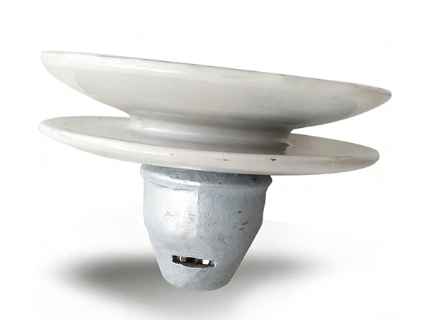
Ball-and-socket connections are the most widely used coupling system for suspension and tension insulators worldwide. The ball on one fitting sits in the socket of the mating fitting, secured by a split pin or locking clip. This design allows rotation in all directions, accommodating the natural movement of the conductor and insulator string under wind and temperature variations without creating concentrated stress points.
The dimensional tolerances for ball-and-socket connections are defined in IEC 60120, which specifies standard ball and socket sizes for different mechanical load ratings. Ensuring dimensional compliance is essential for intercompatibility between insulators and hardware from different manufacturers in the supply chain.
Clevis and Tongue Connections
Clevis fittings feature a U-shaped fork with a pin through the opening, connecting to a tongue fitting on the mating insulator or hardware. Clevis-tongue connections are commonly used to connect insulators to cross arms, pole brackets, and other rigid support structures. The connection allows rotation in one plane (the pin axis), which is sufficient for many fixed-angle mounting configurations encountered in distribution construction.
Clevis connections are also defined in IEC 60120, which specifies the dimensional requirements for clevis pins and tongue openings. Proper fit — not too tight to cause binding and not too loose to allow excessive play — is essential for reliable long-term performance.
Pin-Type Insulator Hardware
Pin-type insulators, commonly used in low and medium voltage distribution, are mounted on a steel or wood pin that is itself bolted or clamped to the cross arm. The insulator sits on a groove in the pin head, and the conductor is tied to the insulator groove using tie wire or a preformed armor grip. The pin must transfer the combined weight of the insulator and conductor, plus any wind and ice loads, to the cross arm without bending or shearing at the attachment point.
Material and Manufacturing Standards
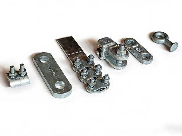
Insulator end fittings are typically manufactured from malleable cast iron for porcelain and glass insulators, or forged or cast aluminum alloy for polymer insulators. Malleable iron fittings offer excellent machinability and strength at lower cost, while aluminum fittings reduce the overall weight of the insulator assembly and avoid galvanic corrosion issues with aluminum conductors.
All insulator hardware must meet the mechanical and dimensional requirements of IEC 60120 and the relevant material standards such as ISO 5922 for malleable iron castings. Manufacturers should provide type test reports including proof-load tests, rupture tests, and corrosion resistance evaluations.
Custom Solutions From Insulator Hardware Manufacturers
While standard fittings cover the majority of applications, some projects require custom end fittings — for example, to connect an insulator to a non-standard cross arm bracket, to meet unique electrical clearance requirements, or to accommodate special conductor configurations. A manufacturer with in-house casting, machining, and galvanizing capabilities can develop custom fitting designs based on drawings, samples, or specifications provided by the customer.
Final Remarks
Insulator hardware connection systems are small but critical components in every overhead line. Specifying fittings that comply with IEC 60120, sourcing from manufacturers with documented quality systems, and ensuring proper dimensional compatibility between insulators and line hardware all contribute to the reliability and safety of the transmission and distribution network.
References
IEC 60120 — Insulator Clevis and Socket Couplings
IEC 60383 — Insulators for Overhead Lines Above 1000V — Test Methods
IEEE 951 — Guide for Testing Transmission Line Hardware
ANSI C29.7 — Wet-Process Porcelain Insulators
We warmly welcome global distributors to partner with us — together we can deliver reliable power line hardware solutions to markets worldwide.
 Recommended Products
 Contact us
—— Contact:Manager
—— Tel:+86 15631793633
—— Email:960244024@qq.com
—— Url:https://www.dachuan-power.com
—— Address:Liugusi Town, Hejian City, Cangzhou City, Hebei Province, China