
NewsDetails
Cable Connector Clamp for Distribution Networks Key Considerations
author:Dachuan time:2026-06-28 21:14:22 Click:115
Cable connector clamps are the mechanical and electrical interface points that join conductors together or terminate them at equipment throughout the power distribution system. From tap connections on distribution feeders to equipment terminals at transformers and switchgear, these clamps must maintain low contact resistance, withstand thermal cycling, and resist corrosion and mechanical vibration over decades of service. For distribution engineers and procurement specialists, understanding the factors that determine cable connector clamp performance is essential for building reliable and maintainable networks.
What Cable Connector Clamps Do
A cable connector clamp creates a permanent or semi-permanent connection between two or more conductors, or between a conductor and an equipment bushing. The connection must carry the full rated current of the conductors without excessive heating — which would cause energy loss and accelerated insulation aging — and must survive the mechanical forces from thermal expansion and contraction, wind-induced vibration, and ice loading.
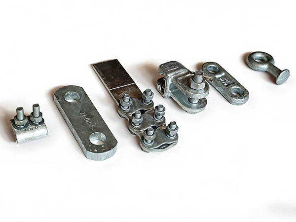
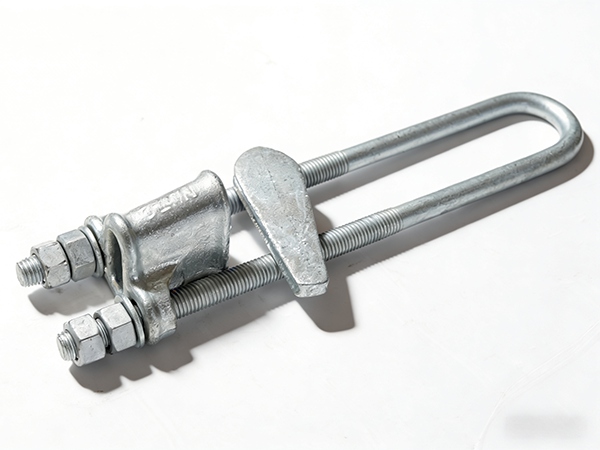
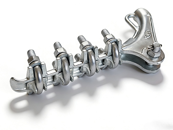
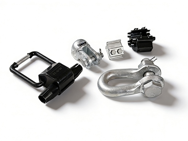
Connector clamps are used in a variety of configurations: inline splices that join two conductors end-to-end, tap connectors that attach a branch conductor to a main feeder, bus connectors that terminate conductors at switchgear or transformer bushings, and dead-end connectors that anchor conductors at pole-top equipment.
Conductor Compatibility and Sizing
Every cable connector clamp is designed for a specific range of conductor sizes, typically defined by the cross-sectional area in square millimeters or the AWG/MCM designation. Using a connector that is too large for the conductor can result in insufficient contact pressure and high resistance at the joint. Using one that is too small may damage the conductor strands during installation or service.
Connectors for ACSR conductors must account for the mixed aluminum and steel strand construction, gripping both the outer aluminum layers and the inner steel core effectively. Connectors designed for all-aluminum or copper conductors may not perform well on ACSR without specific design features such as a steel core gripping component or a shear-off bolt system.
Electrical and Thermal Performance
The contact resistance at the connector joint must be low enough that the joint operates at a temperature close to that of the conductor itself. Excessive joint resistance creates localized heating, which accelerates aluminum oxidation at the contact surfaces — a positive feedback loop that further increases resistance and eventually leads to thermal runaway and connection failure.
Quality connectors are designed to create and maintain the necessary contact pressure over the full range of operating temperatures. Bolted connectors typically use belleville washers or spring-loaded bolts that compensate for thermal expansion and contraction. Compression connectors rely on the permanent deformation of the connector body and conductor strands to create a gas-tight connection.
Environmental and Mechanical Stress Resistance
Cable connector clamps installed on overhead poles face the same environmental stresses as all outdoor hardware: rain, humidity, temperature cycling, UV radiation, pollution, and in some cases, chemical exposure from agricultural sprays or industrial emissions. The connector body must resist corrosion to maintain structural integrity, and the internal contact surfaces must remain clean and oxide-free to maintain low resistance.
Mechanical stresses include conductor weight, wind-induced vibration which can cause fretting at contact surfaces, ice loading, and the forces from thermal expansion and contraction. Connectors must be designed to accommodate these stresses without loosening or developing fatigue cracks over time.
Standards and Certification Requirements
International standards for cable connectors include IEC 61284 for overhead line fittings general requirements, IEEE 48 for power cable terminations and splices, and UL 486B for wire connectors for aluminum conductors. These standards define test procedures for current cycling, short-circuit withstand, pull-out strength, and environmental exposure. Connectors that have passed type testing to these standards carry certifications that provide assurance of minimum performance levels.
Evaluating a Cable Clamp Supplier
Key factors in evaluating a cable connector clamp supplier include the breadth of the product range to reduce the number of suppliers a distributor must manage, the availability of type test reports and certifications, the supplier's ability to provide custom connector designs for specific projects, and the consistency of their production quality. A factory with integrated aluminum casting, stamping, and galvanizing capabilities is well-positioned to deliver consistent quality across a full product line.
Concluding Notes
Cable connector clamps may represent a relatively small portion of total hardware costs on a distribution project, but their impact on system reliability is disproportionate to their cost. Specifying connectors that meet international standards, ensuring correct conductor matching, and sourcing from reputable manufacturers are the most effective ways to minimize connection-related failures over the life of the network.
References
IEC 61284 — Overhead Line Fittings — Requirements and Tests
IEEE 48 — Standard Test Procedures and Requirements for Power Cable Terminations
IEC 62067 — Power Cables with Extruded Insulation for Rated Voltages
UL 486B — Standard for Wire Connectors for Use with Aluminum Conductors
We warmly welcome global distributors to partner with us — together we can deliver reliable power line hardware solutions to markets worldwide.
 Recommended Products
 Contact us
—— Contact:Manager
—— Tel:+86 15631793633
—— Email:960244024@qq.com
—— Url:https://www.dachuan-power.com
—— Address:Liugusi Town, Hejian City, Cangzhou City, Hebei Province, China